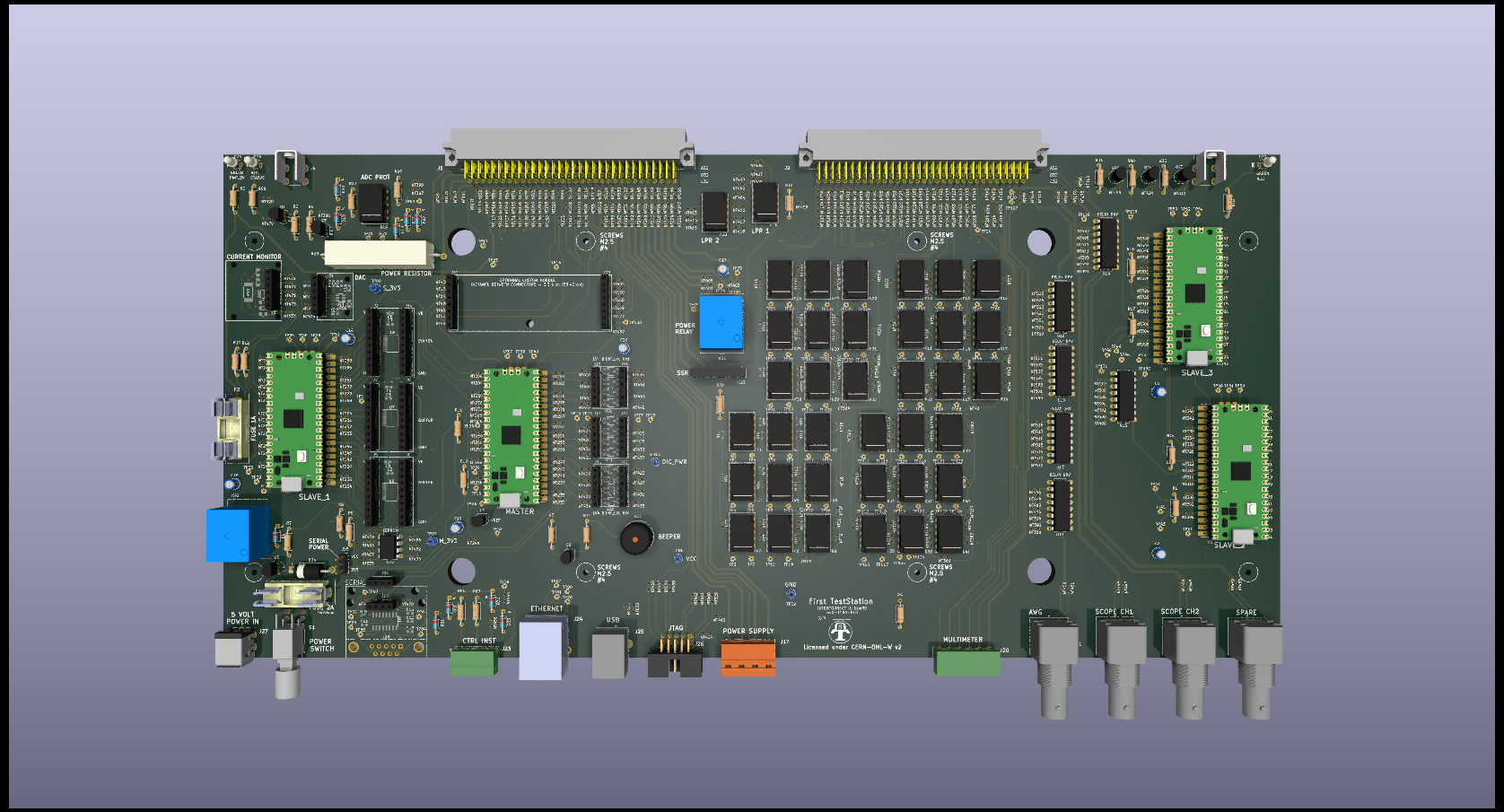
Printed Circuit Board
Interconnect IO Board PCB
Features
• Design of the Interconnect IO board was carried out using the open source software Kicad V7.x.
• Inteconnect Io board source files are available on Github. Link: InterconnectIO_Board
• For mode details, please refer to the electrical schematic.
• On board, hundred of Net Tie components (NTxxx) have been installed to help with on-board modification. The NetTie PCB component facilitates modification routing by providing a clear space where PCB traces can be cut (cut between two holes) and changed routing by adding wire (solder on one of the holes on each side of the trace cut).
• Board users can either use already developed specialized modules available on the market at a low cost, or solder surface-mount components directly onto the board to achieve the same functionality.
• The Pico Board can be soldered directly on the board, but I recommend mounting it on a female socket so that it can be easily replaced.
• In the picture above, only through-hole components are soldered on the PCB. Using piggyback connectors, the specialized module will be mounted on the female sockets.
• For serial interfaces (close to power switches), two different types of modules are available with two different voltages (5V and 3.3V). The voltage will be selected using a female jumper. It is best to use 3.3V, but Pico modules are capable of working at 5V as well.
• The protection fuse is mounted in a socket to make replacement easy.
• There is a reserved area for a custom module that will be added in the future
• The PCB has two soldered screw holders on each side of the 96-pin connector. The purpose of these components is to precisely attach the external mechanical PCB rail to the PCB.
• This board is protected against reverse voltage and high voltage with a 5.5V protection diode (fuse will burn if high voltage is applied).

